I'm periodically sending pulses with the standard bladerf C library. By "pulses", I mean continuous IQ samples of (1+1j)/sqrt(2) during the "on" time. These are generated at a sample rate of 2Ms/s, but are very short, 400 samples or so ~= 200us. I have 1024 generated samples within which are two of the ~200us pulses that I'm transferring. My bladerf buffer size is set to 8192 samples in the config call, so I zero pad the 1024 samples up to 8192 samples while keeping the 1024 signal samples centered in that overall buffer. Then I send, and...not much on the receiver, a HackRF running into GQRX.
Notably, all samples outside of the pulse interval are 0+0j. However, if I add in a CW signal into the entire 8192 sample buffer, I can much more clearly see the pulse in the spectrum at the receiver, along with that CW signal of course. This leads to the question: is there a ramp-up time for the output amplifier, or some output filter that needs to be excited before transmitting the actual signal? Are my pulses too fast, or am I doing something wrong at the receiver? My GQRX receiver is running the smallest FFT size at the highest frame rate to try and catch that ultra fast pulse.
Further info: if I tell bladerf to repeat that 8192 sample buffer many times in a row, I can see the pulses much better at the receiver. But I only need to send them every 1-2 seconds. All this leads me to think that either a filter has a time constant I have to overcome, or I'm not exciting the channel fast enough.
Thanks for any help.
Amplifier Rampup Time for TX?
-
urist
- Posts: 4
- Joined: Fri Dec 29, 2023 3:21 pm
Re: Amplifier Rampup Time for TX?
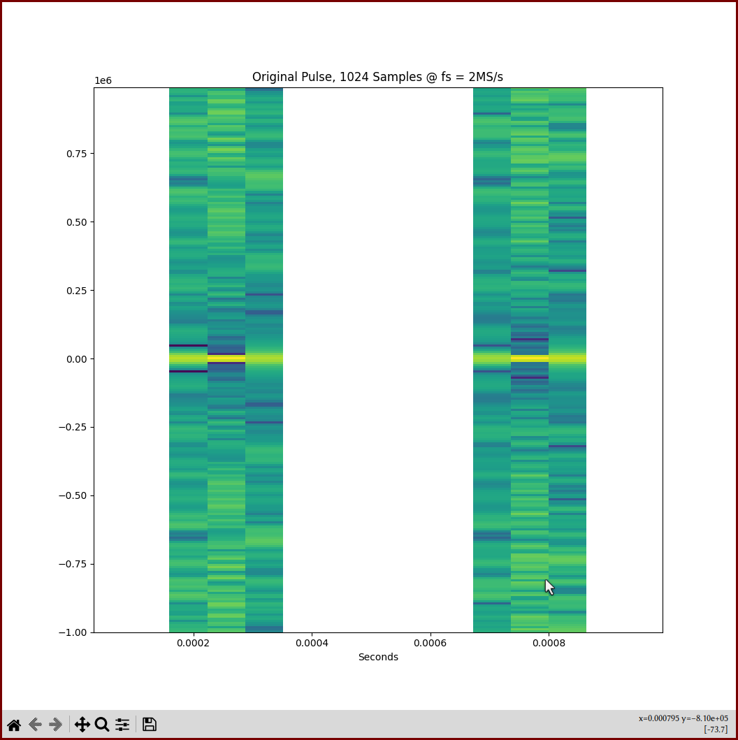
More context. Here is the original 1024 sample pulse:
And the pulse after placing it into an 8192 sample buffer, and also applying the mixins that had seemed to help. Note that the mixins have a max possible sample of (0.001 + j0.001).
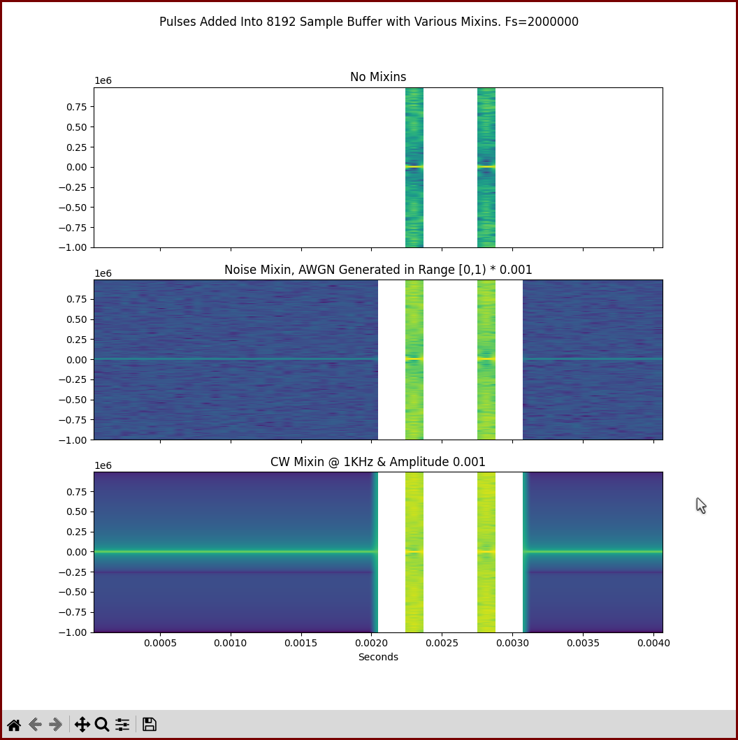
At the receiver, I only see pulse energy in the spectrum if I repeat the above transmissions with noise and CW mixins -- say, 128 repeats or so. That is with HackRF receiver SDR at Fs = 8MS/s and GQRX settings NFFT = 512 and FFT FPS 150, which should be the fastest possible FFT's to try and catch the pulse. Is this most likely a problem at my receiver, or am I generating these pulse bursts incorrectly? I would think that the first subplot in the second figure should transmit fine, but it seems to not.
Thanks.
And the pulse after placing it into an 8192 sample buffer, and also applying the mixins that had seemed to help. Note that the mixins have a max possible sample of (0.001 + j0.001).
At the receiver, I only see pulse energy in the spectrum if I repeat the above transmissions with noise and CW mixins -- say, 128 repeats or so. That is with HackRF receiver SDR at Fs = 8MS/s and GQRX settings NFFT = 512 and FFT FPS 150, which should be the fastest possible FFT's to try and catch the pulse. Is this most likely a problem at my receiver, or am I generating these pulse bursts incorrectly? I would think that the first subplot in the second figure should transmit fine, but it seems to not.
Thanks.
-
[email protected]
- Posts: 6
- Joined: Fri May 20, 2022 4:42 pm
Re: Amplifier Rampup Time for TX?
My first thought is that your receiver running GQRX is running like a swept spectrum analyzer, so that in order for it to see your short pulse it has to be on that particular frequency just when a pulse occurs. Try narrowing the receiver sweep range to be some small bandwidth about your transmit frequency, and you'll be more likely to see the pulses. I'm not too familiar with GQRX, but on a spectrum analyzer you could go into "zero span" mode and make the thing act like a fixed receiver.
-
urist
- Posts: 4
- Joined: Fri Dec 29, 2023 3:21 pm
Re: Amplifier Rampup Time for TX?
You were correct here. Further investigation found that:[email protected] wrote: ↑Sat Dec 30, 2023 8:18 pm My first thought is that your receiver running GQRX is running like a swept spectrum analyzer, so that in order for it to see your short pulse it has to be on that particular frequency just when a pulse occurs. Try narrowing the receiver sweep range to be some small bandwidth about your transmit frequency, and you'll be more likely to see the pulses. I'm not too familiar with GQRX, but on a spectrum analyzer you could go into "zero span" mode and make the thing act like a fixed receiver.
1. There was a buffer size / transfer length problem.
2. More importantly, the library I was using has some sort of issue. Reverting to transmitting via CLI ended up proving to me that my signal generation was fine, but something with the lib was wrong. It is a wrapper around the bladerf lib.
Thank you for your input.
-
TomBrooks
- Posts: 1
- Joined: Thu Apr 03, 2025 9:16 pm
Re: Amplifier Rampup Time for TX?
Consider limiting the receiver sweep range to a narrow bandwidth around your transmit frequency; this increases the chances of detecting the pulses.
-
strakewhip
- Posts: 1
- Joined: Tue Aug 05, 2025 8:21 pm
Re: Amplifier Rampup Time for TX?
Yes, what you're experiencing is likely due to a combination of analog front-end settling time, AGC behavior, and receiver FFT limitations.urist wrote: ↑Fri Dec 29, 2023 3:42 pm I'm periodically sending pulses with the standard bladerf C library. By "pulses", I mean continuous IQ samples of (1+1j)/sqrt(2) during the "on" time. These are generated at a sample rate of 2Ms/s, but are very short, 400 samples or so ~= 200us. I have 1024 generated samples within which are two of the ~200us pulses that I'm transferring. My bladerf buffer size is set to 8192 samples in the config call, so I zero pad the 1024 samples up to 8192 samples while keeping the 1024 signal samples centered in that overall buffer. Then I send, and...not much on the receiver, a HackRF running into GQRX.
Notably, all samples outside of the pulse interval are 0+0j. However, if I add in a CW signal into the entire 8192 sample buffer, I can much more clearly see the pulse in the spectrum at the receiver, along with that CW signal of course. This leads to the question: is there a ramp-up time for the output amplifier, or some output filter that needs to be excited before transmitting the actual signal? Are my pulses too fast, or am I doing something wrong at the receiver? My GQRX receiver is running the smallest FFT size at the highest frame rate to try and catch that ultra fast pulse.
Further info: if I tell bladerf to repeat that 8192 sample buffer many times in a row, I can see the pulses much better at the receiver. But I only need to send them every 1-2 seconds. All this leads me to think that either a filter has a time constant I have to overcome, or I'm not exciting the channel fast enough.
Thanks for any help.
BladeRF TX path: There is some latency and potential ramp-up in DACs, mixers, or filters. Very short bursts (like your 200 µs pulse) can get attenuated or filtered out due to DC blockers or coupling caps needing time to stabilize.
HackRF/GQRX RX path: GQRX may not be fast enough to visually capture such short pulses in real time—especially at low FFT sizes or if AGC is enabled (which can suppress short bursts).
Why CW "helps": Adding a constant CW "warms up" or "excites" the chain, keeping the front-ends active and filters settled, allowing the pulses to transmit and be received more effectively.
Suggestions:
Add a low-amplitude CW or noise floor during the buffer outside the pulse to keep TX/RX chains alive.
Avoid full-zero buffers—hardware often treats these differently.
On the RX side, disable AGC, increase FFT size, or use a recording tool (like hackrf_transfer) to capture raw samples and inspect offline.
Consider sending repeated buffers for reliable detection if hardware latency is unpredictable.
In short: yes, your pulses are likely too short to be reliably caught without pre-excitation or compensation.
https://nuand.com/forums/viewtopic.php?p=19589#p19589
Melon Sandbox characters, items, and weapons that they can use to construct, destroy, explore, and interact in a sandbox setting.
Melon Sandbox characters, items, and weapons that they can use to construct, destroy, explore, and interact in a sandbox setting.