ATSC Transmitter

Working on something interesting? Share it with the community!
drmpeg
Posts: 62
Joined: Fri Mar 01, 2013 3:58 am
Location: Silicon Valley
Contact:

ATSC Transmitter

Post by drmpeg »

I was able to get the bladeRF to transmit a fully compliant ATSC waveform this week. All the credit really goes to Clayton Smith VE3IRR for creating the correct Python flow graph and also fixing an issue in GnuRadio to allow that flow to work. Here's the flow graph.

EDIT (Feb 1, 2014):
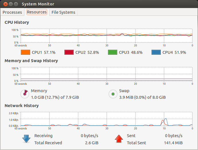
Increased the buffering on the osmosdr sink (buffers=128,buflen=32768). This allows for glitch free operation when other processes run on the host. Even heavy web browsing can be done while transmitting.

EDIT (Feb 27, 2014)
To avoid different versions, the atsc-blade.py script is now being maintained at:

https://github.com/argilo/sdr-examples/ ... c-blade.py

along with a USB2 version:

https://github.com/argilo/sdr-examples/ ... de-usb2.py

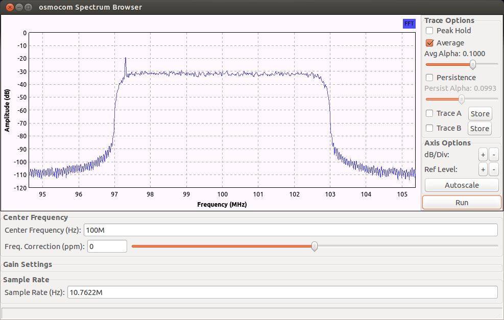
The sample rate is 10.76 Msps, so a USB3.0 connection is required (for atsc-blade.py). I tested the configuration with an AMD/ATI demodulator evaluation board. The eval board shows internal statistics such as S/N, trellis errors, RS errors, constellation and other parameters.
Image
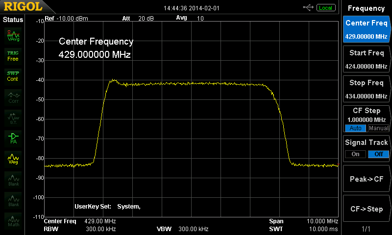
The bladeRF was connected directly to the eval board through a 40 dB attenuator. Here are some results.

The eval board tuned to channel 14 (473 MHz center frequency).
Image
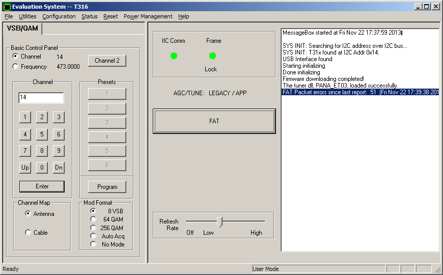
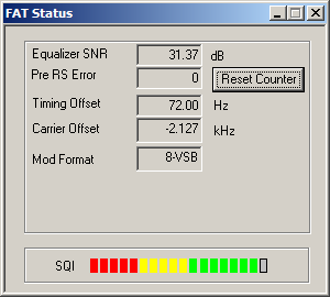
The eval board parameters.
Image
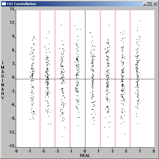
The eval board constellation.
Image

From the parameters dump, we can see that the bladeRF is working perfectly. The equalizer signal to noise ratio is very high at 31.37 dB, no trellis errors and the carrier is only 2 kHz off. The bladeRF power output was adjusted to provide maximum equalizer S/N and ended up at txvga1 gain = -6 db and txvga2 gain = 12 dB. Unfortunately, I don't have a spectrum analyzer, so I don't exactly know what that power level is.

As the final step, the bladeRF was connected (same direct connect with 40 dB pad) to a TV with an internal 8VSB tuner. As expected, it worked perfectly on channel 14-1.

Here's the test stream.

http://www.w6rz.net/advatsc.ts

Ron
Last edited by drmpeg on Thu Feb 27, 2014 9:33 pm, edited 2 times in total.
drmpeg
Posts: 62
Joined: Fri Mar 01, 2013 3:58 am
Location: Silicon Valley
Contact:

Re: ATSC Transmitter

Post by drmpeg »

Here are some spectrum plots of the ATSC transmitter IQ values stored to a file and displayed with osmocom_fft. This shows the effect of using a different amount of taps on the root raised cosine filter.

20 taps.
Image

50 taps
Image

100 taps (the value used for testing)
Image

150 taps
Image

200 taps
Image

Ron
argilo
Posts: 6
Joined: Fri Mar 01, 2013 4:58 am

Re: ATSC Transmitter

Post by argilo »

Hi all,

I'm the author of the code posted above. I'd be happy to answer any questions anyone has. I'm thrilled to hear that the code works on the BladeRF -- I was unable to test it myself because the performance of my USB 3.0 port isn't good enough.

It seems to me that virtually everything in my script could be implemented in the BladeRF's FPGA, so that the BladeRF would take a transport stream as input rather than I/Q samples. In particular, moving the RRC filter into the FPGA would free up a lot of CPU. Does anyone know enough about FPGA programming to comment on the feasibility of this?

73,
Clayton VE3IRR
bpadalino
Posts: 303
Joined: Mon Mar 04, 2013 4:53 pm

Re: ATSC Transmitter

Post by bpadalino »

I concur regarding the RRC filter. That is a no brainer.

The 100 tap response that is in the above post - at what sample rate is that at?

I wonder if a good split might be to have the 8-VSB bit stream (not IQ samples) go down, so each 3 bits turns into the appropriate symbol and the FPGA basically just does the interpolation and RRC filtering (and DC pilot injection maybe?).

I'd be interested in making an ATSC specific FPGA image to load. Let me know how much of this you want to split up, and we can try to get something going?
drmpeg
Posts: 62
Joined: Fri Mar 01, 2013 3:58 am
Location: Silicon Valley
Contact:

Re: ATSC Transmitter

Post by drmpeg »

The sample rate for all the RRC plots is 10.7622 Msps. The exact ATSC symbol rate is based on the old NTSC audio carrier offset of 4.5 MHz and is 4,500,000 / 286 * 684 = 10,762,237.762237762237... symbols/sec.

Here's the CPU load on my Intel E5-1607 (a fairly mediocre 4 core at 3 GHz).

Image

Ron
bpadalino
Posts: 303
Joined: Mon Mar 04, 2013 4:53 pm

Re: ATSC Transmitter

Post by bpadalino »

If you remove the RRC filter (I know you're not transmitting over the air, so the test should be OK) how much lower does the CPU load get?

Is the vast majority of CPU time spent doing the RRC filtering?

With a 100 tap filter, symmetric, and 4 clocks per symbol should turn into something like 26 multipliers to do the whole filtering in the FPGA - probably less since some of those taps are probably going to be very small, or simpler shifts and adds.

I'd be curious how much CPU it takes to do the interleaving, and RS encoding, versus just the symbol shaping filter.
drmpeg
Posts: 62
Joined: Fri Mar 01, 2013 3:58 am
Location: Silicon Valley
Contact:

Re: ATSC Transmitter

Post by drmpeg »

Oddly enough, the CPU usage goes up if the RRC is taken out. CPU usage also goes up if the number of RRC taps is reduced to a small value like 8. Also, a 200 tap RRC doesn't seem to take any more CPU than the 100 tap.

I was reading the Transport Stream file from /dev/shm to avoid any disk access issues.

Based on previous experience with benchmarking embedded systems, it's usually some kind of cache issue. That is, changing the code causes different cache alignments (some more favorable than others). But that's just a guess.

Unless there's some nice benchmarking tool for GnuRadio (is there one?), I'll just try removing blocks to see where big changes in CPU load occur.

Ron
drmpeg
Posts: 62
Joined: Fri Mar 01, 2013 3:58 am
Location: Silicon Valley
Contact:

Re: ATSC Transmitter

Post by drmpeg »

Sending the samples to the osmocom sink (and over USB3.0 to the bladeRF) is the wrong way to benchmark. It seems the throttling to the output sample rate causes the non-intuitive results I posted previously.

A much better way to benchmark is to send the samples to the file sink (blocks.file_sink) and direct that to /dev/null. This provides much more coherent results.

Without the RRC, it takes 24 seconds to process a 105 second TS file. With the 100 tap RRC, it takes 58 seconds. So the RRC takes more that half of the total cycles (around 60%).

Ron
bpadalino
Posts: 303
Joined: Mon Mar 04, 2013 4:53 pm

Re: ATSC Transmitter

Post by bpadalino »

Have you given the new ControlPort (warning: PDF) in GNURadio a shot?

That looks like it might be able to tell you the profiling information.
argilo
Posts: 6
Joined: Fri Mar 01, 2013 4:58 am

Re: ATSC Transmitter

Post by argilo »

bpadalino wrote:I wonder if a good split might be to have the 8-VSB bit stream (not IQ samples) go down, so each 3 bits turns into the appropriate symbol and the FPGA basically just does the interpolation and RRC filtering (and DC pilot injection maybe?).
That sounds like as good a spot as any to split the processing. The steps to get from MPEG transport stream to 8-VSB symbols are all bit shuffling, and they're not CPU intensive. Of course, it would be nice to have them in the FPGA someday.

The steps to get from 8-VSB symbols to I/Q samples are:
  • Represent the eight symbols as complex numbers: -7, -5, -3, -1, 1, 3, 5 and 7.
  • Add 1.25 to each symbol. (This injects the pilot tone. Obviously this could be combined with the previous step.)
  • Shift the signal down in frequency, by multiplying it with a complex exponential with a frequency of -2.691 MHz. (We want the final ATSC signal to extend from -3 MHz to +3 MHz and the pilot tone is supposed to be 309 kHz above the bottom of the channel. So we want the pilot tone to be at -2.691 MHz, while up to this point it was at 0 Hz.)
  • Filter the resulting signal with a root raised cosine filter with alpha=0.1152 (per the ATSC specification). Since the signal was shifted down in the previous step, the RRC filter removes most of the lower sideband and a bit of the upper sideband, giving a signal that sits between -3 MHz and 3 MHz.
All this takes place at a symbol/sample rate of 4.5 MHz * 684 / 286, which is about 10.7622 MHz.

Of course, somewhere along the way you should make sure the gain is such that the resulting I and Q values stay between -1 and 1. I do that by setting the amplitude of the complex exponential in the third step to 0.9, which seems to work well.
bpadalino wrote:I'd be interested in making an ATSC specific FPGA image to load. Let me know how much of this you want to split up, and we can try to get something going?
I'm an FPGA beginner, so having some sort of template (including a FIR filter) to start working with would be a big help. Unfortunately I have another big project on the go that will be taking up most of my free time for the next few months, so I might not have much time to work on this until March or so.
drmpeg
Posts: 62
Joined: Fri Mar 01, 2013 3:58 am
Location: Silicon Valley
Contact:

Re: ATSC Transmitter

Post by drmpeg »

ATSC signal from bladeRF on the spectrum analyzer.

Image

Ron
argilo
Posts: 6
Joined: Fri Mar 01, 2013 4:58 am

Re: ATSC Transmitter

Post by argilo »

I just added atsc-blade.py to my sdr-examples repository on Github:

https://github.com/argilo/sdr-examples

Also I made a few changes:

https://github.com/argilo/sdr-examples/ ... a58bf33e9c

I changed the transmit frequency to be in the 70cm amateur band, increased the output gain and replaced the three blocks I had been using for symbol coding (uchar to float -> multiply const -> add const) with a single "chunks to symbols" block.
argilo
Posts: 6
Joined: Fri Mar 01, 2013 4:58 am

Re: ATSC Transmitter

Post by argilo »

I also made a second version of the transmitter that works well on USB 2.0. It reduces the output sample rate down to 2/3 times the symbol rate so that less USB bandwidth is required.

https://github.com/argilo/sdr-examples/ ... de-usb2.py
argilo
Posts: 6
Joined: Fri Mar 01, 2013 4:58 am

Re: ATSC Transmitter

Post by argilo »

I've also eliminated two more unnecessary blocks, by having the "Chunks to Symbols" block output complex numbers:

https://github.com/argilo/sdr-examples/ ... f10f5c17ba
unwiredben
Posts: 3
Joined: Tue May 27, 2014 3:33 pm

Re: ATSC Transmitter

Post by unwiredben »

I've been using the combo of the BladeRF and this script to do ATSC testing on our Roku TVs now for several months. I had one question -- if I use this script with a transport stream that was originally captured as a low-bitrate subchannel, it looks like there's no padding inserted, so our TV plays the video at a high speed. Does anyone know of a good way to insert padding into the TS so it wll play at the proper speed? Doing it automatically as part of this script would be excellent.
Post Reply